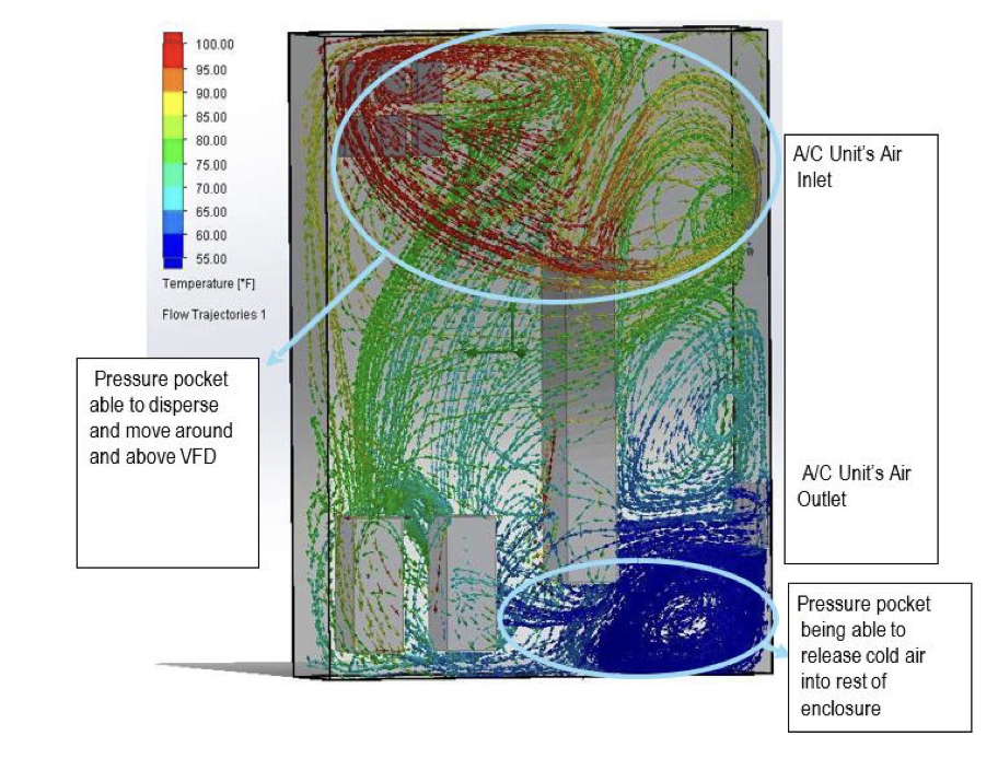
Test Scenario #3 pushes the blockage to 12 inches of total distance between the A/C unit’s air outlet and drive. This unit has the lowest chances of short cycling out of the three scenarios. Additional airflow can get across and reach the other side of the enclosure because the pressure pocket in the lower right corner disperses under the drive and to the rest of the enclosure. The large pressure pocket of hot air that formed in Scenario 2 is completely dispersed; the airflow path can travel at the top and around the drive while still being able to cool the large drive. The airflow from the two smaller drives can push cooler airflow near the contactors and is able to carry the heat from them and bring it to the A/C unit.
Scenario #3 presents the least possible likelihood of short cycling cold air being redirected into the A/C unit and all components have airflow going to them. Scenario #1, had the highest chance of short cycling overall which would cause the unit to shut off early and not cool the enclosure to the desired temperature. Scenario #2 featured a large pressure pocket of hot air that would not be able to cycle correctly and would end up causing most of the contactors to overheat.
While these scenarios are simulated, and may not exactly replicate real world conditions, they can be used as best practices when designing the enclosure layout. For example, the scenarios showed that, as the blockage was pushed further out, there was better airflow in the enclosure, but it became apparent that the large drive’s exhaust air was blocking airflow in the cabinet. This is why components with larger fans internally should typically be mounted farther away from the A/C unit to help cycle airflow throughout the enclosure.
Another common misconception is that since the large drive is the most sensitive component, it would need to be mounted as close as possible to the A/C unit to receive the coldest air.
This is incorrect, because it would end up restricting airflow for the other components inside of the enclosure. Instead, it should be mounted farther away from the A/C unit. This would allow for airflow to travel towards it and would support a full circular motion of airflow throughout the enclosure.
Other design considerations
When designing electrical enclosures for optimal air circulation, engineers should consider the following:
Ventilation and cooling systems
Integrating ventilation and cooling systems, such as fans or heat sinks, can complement the effects of component spacing. These systems can further enhance heat dissipation within the enclosure. Using enclosure fans inside electrical enclosures are a great way to help move air within the enclosure. In scenarios where possibility of repositioning components is limited, enclosure fans can be installed to help ensure air is reaching all points of the enclosure.
Enclosure material and color
In outdoor applications or hotter environments, heat transfers into the enclosure from the hotter ambient air through the metal enclosure or from the sun hitting the enclosure. Using a darker color absorbs more heat from the sun, while use of a light color reflects the heat from the sun and has less likelihood of solar loading. Every metal has a heat transfer coeffcient and can affect the amount of heat transfer from the environment into the enclosure and vice versa. Insulation can be used on the inside of the enclosure to help prevent the ambient environment’s heat transfer from affecting the enclosure. Alternatively, a sun roof can be used to keep the sun from directly hitting the enclosure to prevent solar loading.
Enclosure mounting style
The amount of surface area of the enclosure can affect the amount of heat transfer to the environment if the ambient environment is cooler than the enclosure, or the amount of heat transfer to the enclosure if the ambient environment is hotter than the enclosure. Surface area is often overlooked as a factor that can lead to large amounts of unplanned heat inside the cabinet due to heat transfer from the ambient environment. For example, there is no need to factor the heat transfer from the back of the enclosure if the enclosure is mounted up against a wall.
Achieving a better enclosure system design
To ensure smooth and successful operations, companies can strategically space and position components within electrical enclosures to enhance air circulation and mitigate hot spots. Proper spacing strategies empower companies to optimize air circulation, effectively dissipate heat, and improve overall system performance. Use of CFD analysis helps companies design enclosures that factor in enclosure temperature and air flow. Other considerations, like integrating ventilation and cooling systems, enclosure color, materials, and mounting style, all play a part in achieving the best overall system design.


