THE LOW RESISTANCE OHMMETER appeared just over a century ago, at the dawn of the electrical industry and the development of test instrumentation. A genuine low resistance ohmmeter is designed to measure less than 1Ω. Accordingly, it must have sufficient test current to accurately measure to minute levels. This is a critical differentiation from common resistance functions appearing in multi-purpose instruments like DMMs. A good DMM may measure down to 0.01Ω. By contrast, a good low resistance ohmmeter will measure to 0.1 micro-ohms (μΩ). Such precision calls for considerably more test current than can be achieved from a few milli-Amps.
For over a century, the standard test current for low resistance ohmmeters has been 10 Amps. But many standard values in electrical testing are not necessarily derived rigidly scientifically but by a process that includes compromise and practicality. A DMM can give you a hundredth of an ohm with milli-amp test current, but to range down to a millionth, you need a robust test current and so 10 Amps became industry standard…and remained so for about a century. Twenty-First Century advances in the operation, precision and reliability of test instrumentation has made it possible for smaller test currents, where desirable, to be applied without loss of reliability and repeatability. What does that gain for the operator?
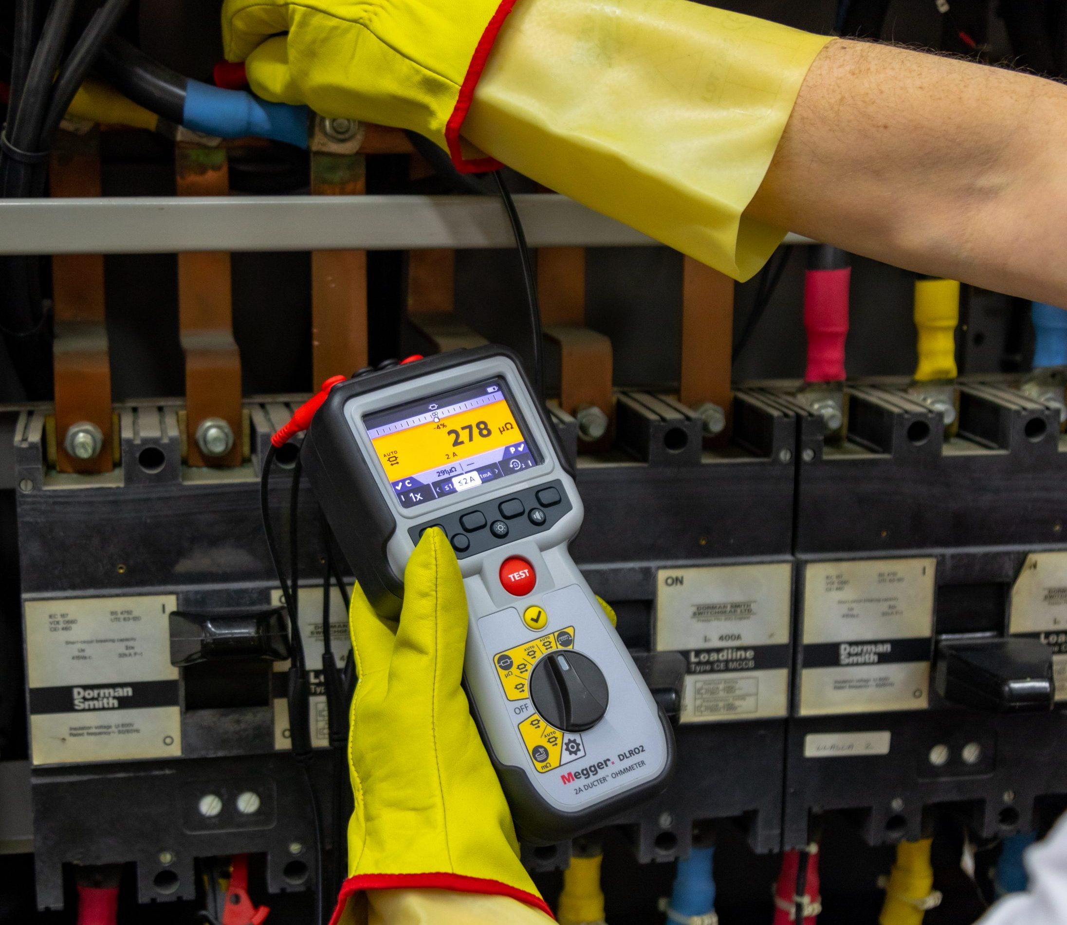
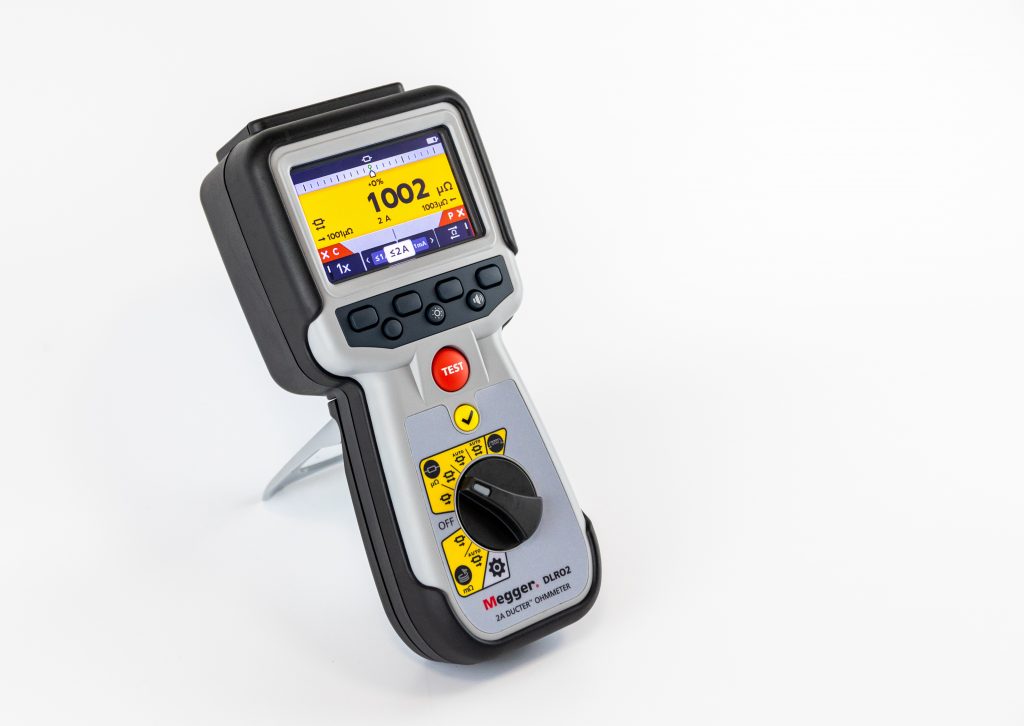
One immediate benefit is size reduction, down to a conveniently handheld instrument. Traditional models have been reduced in size and weight over recent years, but mainly in small increments. We now have available conveniently handheld models that test at 2 Amps. This is a revolutionary combination of vigorous testing current with operator convenience. But the first and most indispensable requirement to look for in size reduction of any electrical test equipment is arc flash safety. If an “event”…as the utilities like to call them…occurs on the line, the operator needs to be fully protected against arc flash/blast that can otherwise be lethal! The reliable measure of this is the IEC61010 Rating. Do not buy an instrument that is rated below the standards of your work. As the casework becomes smaller to fit the operator’s hand, maintaining IEC safety becomes a challenge. Electrical components must have sufficient creepage and clearance distances to preclude deadly arcing within the instrument. Be sure to understand that the CAT rating (III or IV) of the instrument matches that of the work environment and also includes a maximum voltage rating for the system.
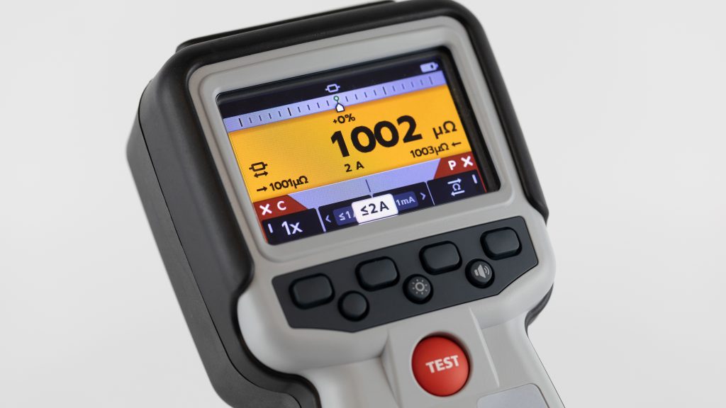
Having met the basic challenge of size reduction without current compromise or loss of safety opens a cornucopia of additional conveniences that can be built into state-of-the-art models. Testers of years ago focused on the measurement, and older testers are often equal to modern ones in that regard. But they may have offered little else. Today’s 2A testers typically can measure a range like 1 μΩ to 2kΩ with 1% accuracy, but also offer speed, less down time, and minimal chance for error. Displays provide a plethora of information that keeps the operator focused with less chance of mistake while testing quickly. Full-color displays are not just for snazzy looks. By simultaneously displaying additional test information delimited by a color pattern, the operator can move swiftly and error-free without having to put down the instrument, check other sources, and so on. A prime example is a “Difference Meter” function. This function will display a series of measurements not by their hard numbers but by the difference from a base measurement. Operators can check connections to a panel board, a series of similar connections and the like in seconds, without reference to any other document. The display positions them along a scale with % change from baseline with convenient notations to catch the operator’s attention. Hard numbers are also retained, not discarded. The difference function substitutes for constant reference to pass/fail criteria, a valuable saving in time and potential mistakes.
Another vital function is the ability to safely test inductive loads. With a dc test, some test items can store enough energy to be lethal if not judiciously tested. A modern tester helps! With a selected inductive mode, current can be limited to 1 A for faster charging, quicker result that still meets all parameters. Particularly adapted for items like small electric motors and power transformers, these items must come to full charge before precise, reliable measurements can be made. Otherwise, the charging process merely confuses the operator and lends to incorrect results. The display will indicate that this process is underway and not complete. An added capability that the tester may have is an AUTO mode that senses when the IUT has come to full charge and then stops. This is a valuable function in saving time and error, especially for relatively inexperienced operators, as charging can introduce a confusing element of instability that can waste time and lead to errors.
A vital function largely unheard of not many years ago but of ever-increasing importance in modern industry is the use of especially long test leads. These can load down a tester and defeat the test in a model not properly designed for it. But the emerging industry of wind power makes this function a necessity. The high, revolving blade tips are inviting targets for lightning strikes that can do debilitating levels of damage in the wink of an eye! The grounding conductor that protects the blade can be under considerable stress and must be regularly tested. Long test leads of some 300 feet can be burdensome to the tester, but the selection of a 1A test significantly speeds the successful completion of the circuit while allowing a lighter gauge wire that produces a reliable result in seconds. Lightning protection in aircraft can be easily measured wing tip to wing tip. Lightning protection in general is becoming more important with the increased use of sensitive computer-controlled equipment, and long test leads are invaluable in the maintenance of lightning protection.
Another significant time-saving feature is advanced fuse protection. Yes, the operator and instrument must be protected from accidents and faults that can occur beyond the operator’s influence. But this needn’t be expressed in repetitive annoying fuse failures that interrupt testing and drastically eat up time. A quality tester can have active protection against inadvertent live connection without blowing a fuse. Protection up to 600 V is standard while a backup fuse protection at 1 kV keeps the operator safe against catastrophic events.


