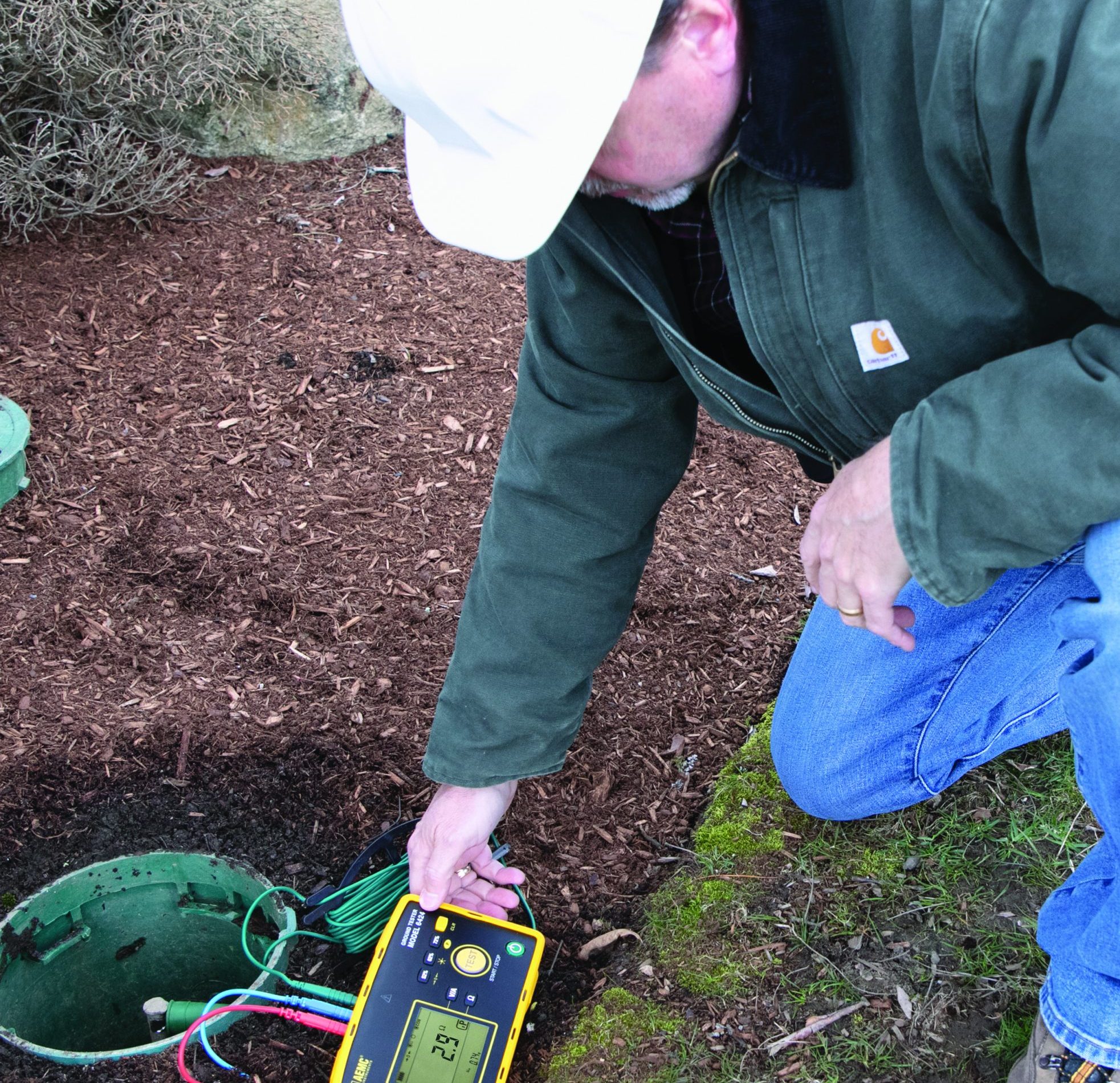
Now let us look at AEMC’s new Model 6424 Ground Resistance Tester. It is understandable that for those who need to perform ground resistance testing on a sporadic basis remembering all requirements involved in properly conducting a fall of potential test can be easily overlooked.
The Ground Resistance Tester Model 6424 offers several novel features and advantages for testing grounding electrode systems.
Main functions include:
2-point test (2P): When turned on, the Model 6424 is initially in the 2-point mode. In this mode, the 2P symbol ap- pears on the bottom right side of the screen. The main display shows the resistance measurement while the bottom of the screen shows the voltage between the H and E terminals. In this mode the instrument can be used as an ohmmeter to check bond resistance and general resistance measurements. Measurements are taken between the red H terminal and the green E terminal. This change confirms that the injector auxiliary electrode (H) is connected before a fall of potential test is conducted.
3-point test (3P): Pressing the TEST button initiates 3P mode. The 3P symbol is displayed on the bottom right side of the screen. The TEST button blinks red while the measurement is taken. When the measurement stabilizes, TEST stops blinking and turns green, indicating the completion of the test. The resistance measurement is displayed and automatically held. The bottom display shows the resistance of the injector electrode (RH) and the voltage used to conduct the test (UH-E).
A unique feature of the Model 6424 is its ability to store the three resistance measurements used to complete the simplified 62% ground test (52%, 62% and 72%) and calculate the average percentage difference between them saving time and ensuring accuracy. After a measurement is taken and stabilized and the test button turns green, simply press the percentage button associated with the Potential electrode (S) distance used for the measurement (for example 52%). The reading will be stored and displayed at the bottom of the screen, and the instrument will return to the 2-point mode. Move the S electrode the next test distance (62%) and repeat the process and store it. Then do the same for the 72% measurement.
When all three readings are stored, they will be displayed on the bottom line of the display and the average and percent deviation will display at the top of the screen. If the percent deviation is above 5% the display will blink indicating the test electrodes are within the influence of each other which will indicate that the injector electrode needs to be moved out further and the three tests repeated.
The model 6424 also can detect haz- ardous voltages up to 700 Volts AC or DC and prevent the test from starting while alerting the operator of a safety hazard. An optional current probe (Mod- el MN72) accessory facilitates leakage current measurement as well to further assist in troubleshooting.
Key features that will especially assist the users who perform ground resistance testing on an infrequent basis are:
Simple operation
- Only one button to press (no set up required) to get test results
- Test button turns green when measurement is stable, turns red if an error occurs
- Ensures that the measurement is valid when button remains green
4 Instruments in one, saves time checking the complete system
- Measures ground resistance
- Checks bond resistance
- Detects hazardous voltages
- Measures leakage AC current
- Color coded inputs and test leads
- Fast error free hook-up and operation Large back-lit digital display
- Easy to read in all lighting conditions Automatic hold function
- Retains last measurement after the reading stabilizes
- Automatic test frequency selection between 128 and 256 Hz
- Provides stable results in adverse environments
Stores 52, 62 and 72% measurements
- Eliminates the potential error in determining the ground resistance
- Built-in test lead compensation capability
- Improves the accuracy of low resistance measurements
- Automatically checks the injector lead connection when connected to the H auxiliary rod
600V Cat IV rated
- Provides a high level of operator safety
Whether you are an infrequent or daily user of ground test equipment, the AEMC model 6424 greatly reduces the possibility of testing errors while ensuring confidence that the measurements are valid in a simplified process. It also provides a high level of safety and alerts to hazardous conditions.


