

ELECTRIC VEHICLES ARE HEADLINE NEWS, BOTH POSITIVE AND NEGATIVE.
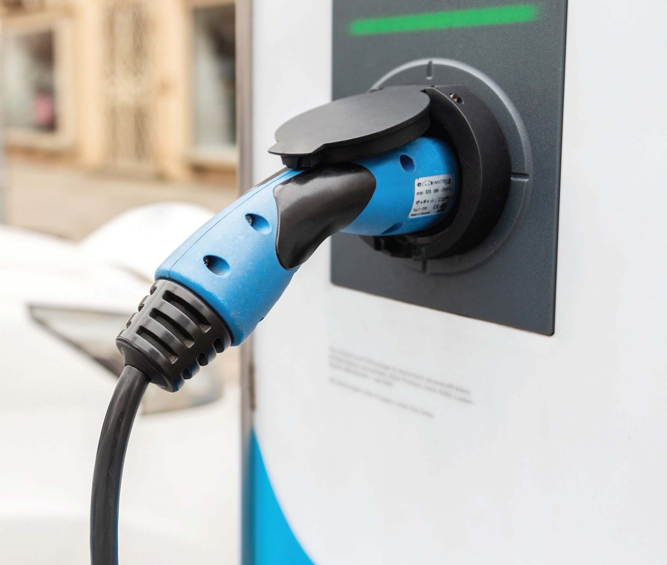
There have been negative reports of safety issues like car fires. But more important, industry trends fueled by controversy over global warming and issues of the environment and pollution have made electric vehicles the trend of the future. Amid such excitement, it’s easy to overlook fundamentals and to ride crests. Don’t neglect to cover all bases, none of which are more important than safety. The charger is a dynamic connection between the almost infinite power of the utility grid and the volatile potential of the car battery, sometimes with a tank of gasoline only inches away in the case of hybrids. Be certain to maintain this vital link with regular and thorough safety maintenance of your charger.
There are seven fundamental tests that an Electric Vehicle Charger Tester should perform; four for safety, one to eliminate nuisance tripping, and two operational tests. These tests are vital and important to perform following installation or repair, to check that the charger meets manufacturing specifications and performance, and as part of any preventive/predictive maintenance program to keep equipment operating and to prolong its life. It is important to perform the tests in a proper sequence, so that the safety checks are established first.
Safety
1.1 Protective Earth (PE) touch pad: The charger being tested is plugged into the power feed as it would be during operation. But now, the EV charger tester takes the place of the vehicle for the performance of the tests. The first is to assure that the protective grounding is in place in the charger. Since during normal operation the charger will be connected to utility power, it is of primary importance to the operator and anyone else who may come in contact that the protective grounding is in place and fully functional. The charger tester will apply a charging code to the charger to put it into the charging state. The protective earth contact test will detect if a ground connection is not present. This test is not a genuine bonding test and does not verify the current-carrying capacity of the ground connection. It verifies the connection’s absence or presence, typically by a PROCEED or FAULT message on the display. The latter message indicates a need for troubleshooting and repair by a qualified electrician. Further testing with the charger tester is disabled.
1.2 Protective conductor resistance (R PE): Next, a Protective Earth Resistance test is performed between the ground pin on the charger socket and a socket on the tester’s handle. This is to check that ex- posed metalwork on the charger is effectively connected to the ground pin on the charging socket or plug. An alligator clip or pointed probe is used to test every point of possible concern. It is not required for chargers that have no exposed metalwork or are double insulated. A practical pass/ fail limit is 0.5 Ω. The tester will typically show both the resistance value and a pass/ fail indication, such as a green check or red X. Again, a failure indication calls for repair by a qualified electrician.
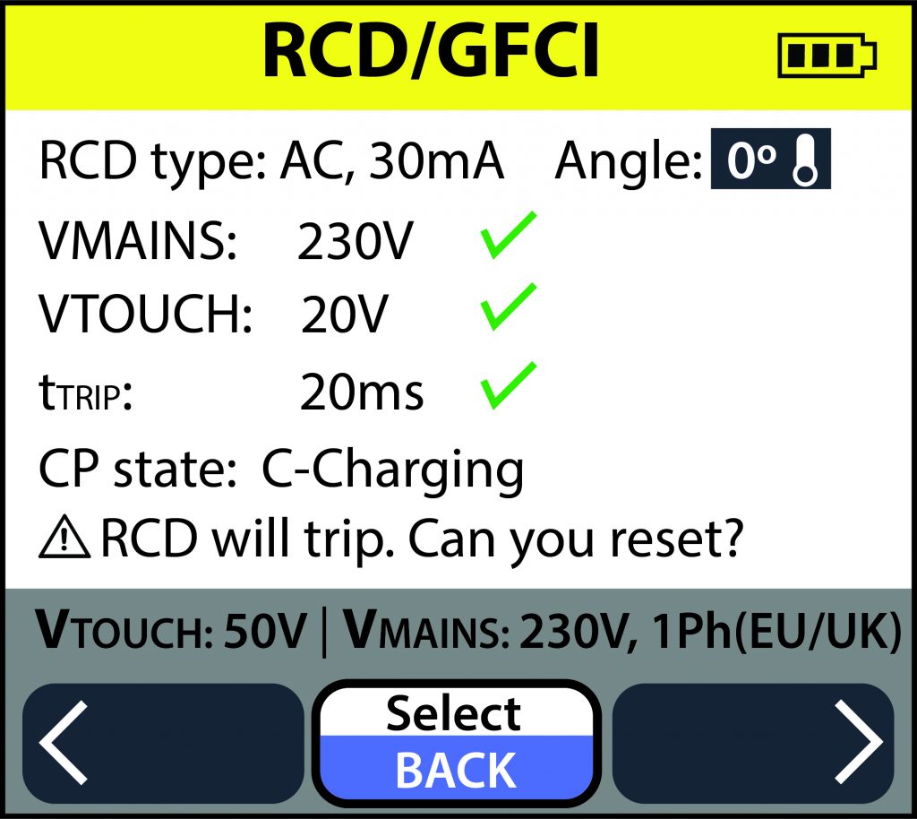
1.3 Touch Voltage measurement & 1.4 Trip Time measurement: Redundant safety protection is afforded the operator of the charger by the inclusion of a GFCI (Ground Fault Circuit Interrupter) or RCD (Residual Current Device). This must be checked. They work by detecting an imbalance in circuit current. Less current returning indicates an unwanted flow to ground. This could be through personnel, causing shock or electrocution, or through equipment or materials, igniting a fire. But this current imbalance will trip the protective device, protecting personnel and the physical plant. The charger tester will apply a calibrated current matching the ratings of the charger’s protective device and measuring how long it takes the device to trip. The tester further checks that the reaction time is fast enough to protect users from electrocution in the event of a charger fault. The test is typically configurable by rated charger voltage (230, 120), test current (30, 20 & 6 mA), and maximum test time (300 ms, 12.5 s, 5.59 s), indicating pass or fail at conclusion.
A tester will typically perform with 0° or 180° earth leakage current. This sets whether the current flow starts at the positive or negative direction zero cross-over. The tester will first put the charger into charging mode and measure the output voltage. It will then perform a touch voltage test, to ensure that the charger ground will not rise to a hazardous voltage. Typically the operator selects be- tween 25 V or 50 V. If the touch voltage test is passed, the tester will perform the selected earth leakage current test. The result is displayed in milli-seconds.
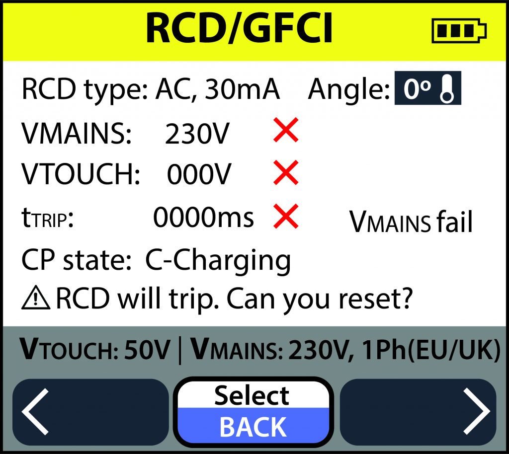
Should the charger fail to switch on the output voltage, the test will stop. This could indicate a connection or fuse problem. Should the touch voltage test fail, this indicates poor connection to protective earth. A qualified electrician should examine for repair. The RCD or GFCI is checked according to pre-set limits based on line voltage, indicated by green check or red X. The latter indicates replacement with new GFCI or RCD.
Nuisance Tripping Test
While the built-in protective device in the charger provides vital safety protection to the operator, it can also be subject to extraneous influences that cause “nuisance” tripping. This can be from sources like the capacitive charging of long extension cables. Such tripping can be a considerable hindrance to rapid and efficient testing, but can be recognized and eliminated by adjustment.
The nuisance tripping test applies a calibrated earth ground leakage current starting at approximately half the trip rating of the protective device, then steadily increases the current until the device trips. The actual current at which the device trips is displayed. If this value is low, there is a high probability that the charger will exhibit nuisance tripping. Typically, the tester can perform this test in four ways.
a) An AC current trip at 230 V ramps up to 30 mA in 2 mA steps of 300 ms duration, for a test time of 4.5 seconds.
b) A DC current trip ramps at 6 mA for 2.5 seconds to prevent tripping of the AC response, then holds at 3 mA DC for 11.25 seconds.
c) For 120 V equipment, a 6 mA AC test ramps up in 0.5 mA steps of 100 ms duration for 4.5 seconds.
d) A similar test at 20 mA ramps up in 1mA steps of 100 ms duration for a max time of 2 seconds.