

IN FUNDAMENTAL DESIGN, TRANSFORMERS ARE RATHER SIMPLE DEVICES. Two coils of wire are wound together on an iron core. These are referred to as “windings”. One is connected to a power source and designated the “primary”. The other provides power to a load and is called the “secondary”. Energy transfer occurs via magnetic induction and is “transformed”. The more “turns” there are to the winding, the more impedance there is, and hence the higher is the voltage that is generated across it.
But as nothing is “free” in nature, the higher voltage is achieved at the cost of current. If the secondary has more turns than the primary, voltage is increased, but with less current. This constitutes a “step up” transformer. Conversely, reverse the winding ratio and it creates a “step down” transformer, with lower voltage and more current.
Having “no moving parts”, so to speak, such a device can and does run for years. But they are not perfect and transformers can and do break down. Such occurrences can be nothing less than cataclysmic and must be prevented. An effective method for detecting, and hence addressing, impending failures is called turns ratio testing.
A direct and useful relationship exists between the number of turns and the voltage ratio between primary and secondary. It is expressed by:
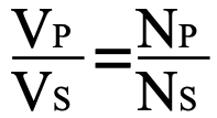
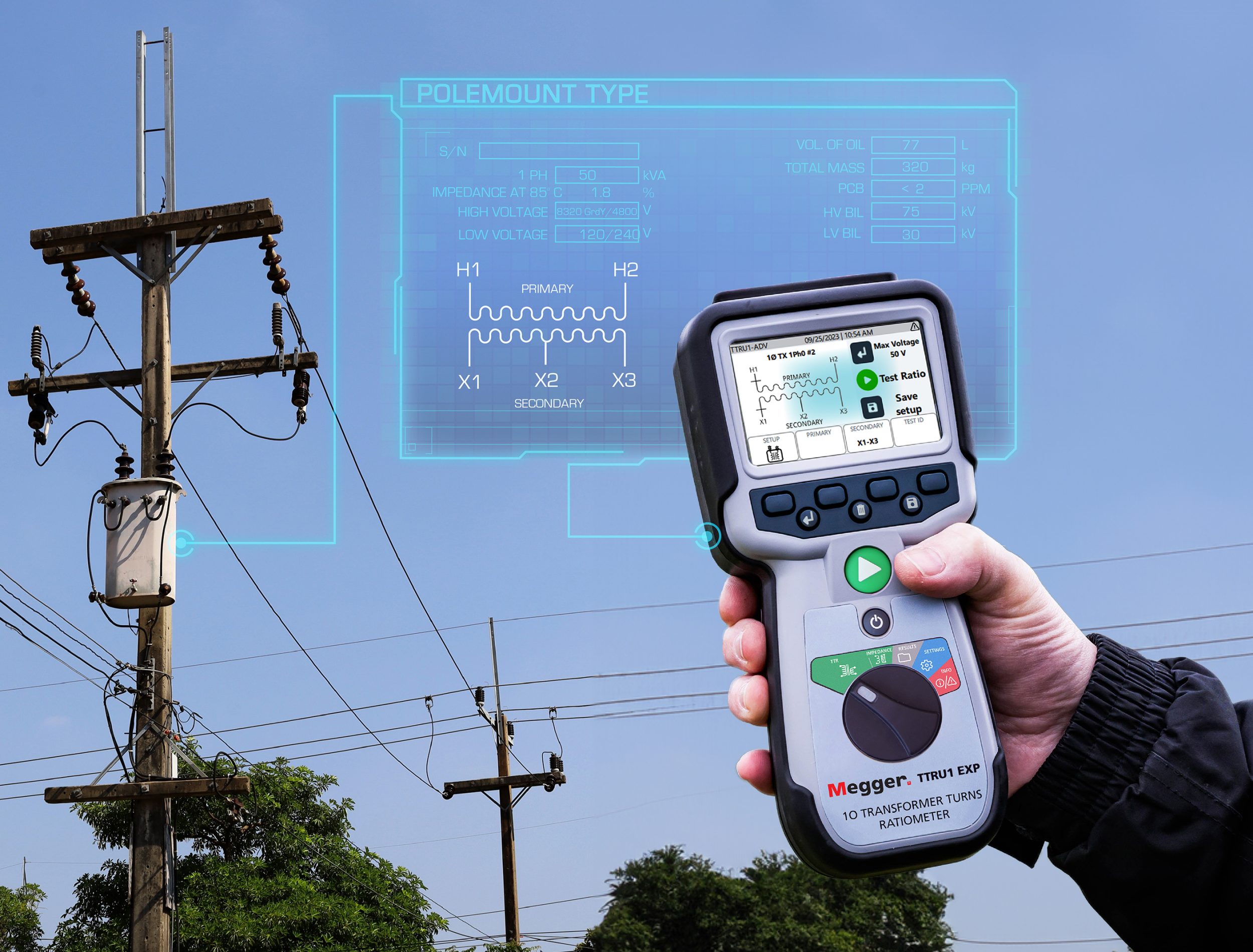
where VP = primary voltage, VS = secondary voltage, NP = number of primary turns, and NS = number of secondary turns. Standard notation designates the high-voltage winding “H” and the terminations H1 and H2. The low-voltage winding is notated “X”, with the terminations X1 and X2. The source voltage can be connected to either set of terminals, depending on whether the transformer is “step up” or “step down”. This fundamental relationship is the basis for one of the most effective methods of testing, evaluating, and maintaining transformers in prime condition. It is called Turns Ratio Testing. In service, a plethora of causes can damage or deteriorate insulation around windings. Shorts between turns allow current to flow directly to the next turn, effectively reducing the number of turns and altering the turns ratio. Periodically measuring the turns ratio, therefore, provides a valuable indicator of the overall health and condition of the transformer and keeps the maintenance program well informed in time to head off any serious consequences. A transformer will tolerate a limited amount of such deterioration, but it’s a predictor of ultimate failure. So much so that ANSI Standard C57.12 specifies that turns ratio be within 0.5% of rating.
Direct measurement of output voltage, however, is difficult and dangerous, plus lacks the accuracy necessary to make
an exacting calculation. Furthermore, disturbances to the source voltage could produce erroneous calculations. Voltage measurement for turn ratio calculation must be performed by a dedicated instrument designed with requisite performance characteristics and sensitivity. A traditional hand- cranked turns ratio tester (TTR) is a reference transformer modified to be balanced against a load (the transformer under test), measure the balanced voltages to high accuracy, and calculate the ratio. The voltage ratio at “no load” (balanced) condition is the turns ratio. To meet the ANSI standard, the tester must measure voltage to at least 0.1% accuracy, hardly attainable with a common voltmeter. Turns ratio testing is performed on de-energized transformers with the tester providing the current. The reference transformer and the IUT are connected in parallel and balanced so that there is zero circulating current and voltage, without burden on either transformer.
The traditional TTR is a fairly large piece of equipment, circa 20 pounds and carried by a shoulder strap. They are constructed for hard usage and may be powered by a hand crank. Decade knobs required the operator to manually balance the load against analog meters, an exercise that could be tedious. Test results were fairly narrow in the amount of information they provided. Modern advancements in microcircuitry have notably simplified and improved on the old, more labor-intensive routine for transformer turns ratio testing. Some old format testing will still be required for the most demanding job sites. But taking advantage of modern upgraded entries to the equipment pool can save considerable time and effort while broadening the scope of test results with maximum accuracy, reliability and safety.
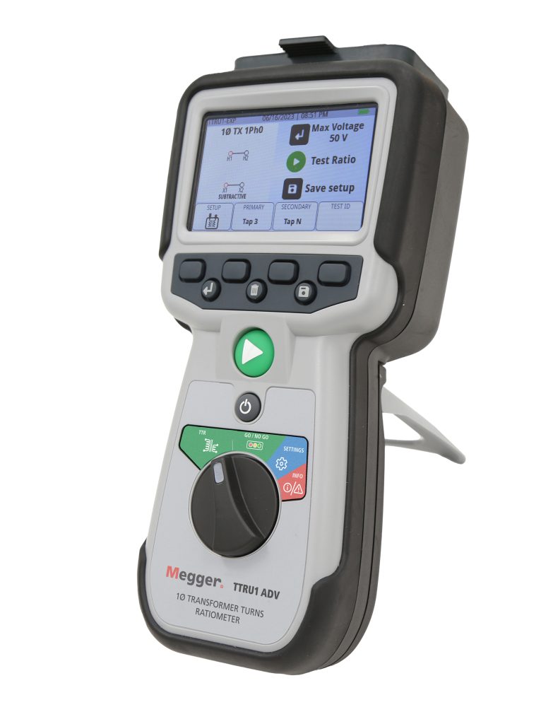
Modern Turns Ratio Testers can now be handheld instruments. They include battery-powered single-phase models that are quick and convenient to operate, up to 250 V AC with 0.05% accuracy. They can be used on single- and 3-phase distribution, power and instrument transformers for ratio, polarity and verification. Dedicated instructions guide the operator through 3-phase setup and application so that no operator error threatens the success of the test. The operator is not required to know the test voltage, as modern instruments utilize single-phase step-up ratio technologies to overcome voltage dependence when testing large transformers. The prospect of operator error is further reduced by color-coded leads and customizable on-screen vectors and voltages to match the transformer’s nameplate.


New built-in capabilities include convenience features like full-color displays, replacing the old analog meter guesswork. Pass/fail ratio evaluation, auto result saving, customizable vector list and asset nameplate, and simulation mode software provide the operator with additional diagnostic help. Powered by AA NiMH batteries, a modern tester can perform up to 1000 tests on a single charge. Recharging batteries is a simple process, using built-in USB and connecting to any standard USB wall charger. Modern testers also provide go/no-go short circuit and open circuit identification, and inductance, short circuit impedance and reactance. Additive/subtractive polarity designation and excitation current display further aid the operator in analysis, diagnosis and evaluation. Phase deviation is another valuable diagnostic and analytic tool now available.
Turns ratio testing requires high precision. A traditional challenge was associated with balancing test voltage against the leads. Modern testers now automatically apply proper test voltage against shorting connections. Safety should always be a paramount consideration and CE certification to IEC 61010 provides dependable and demonstrable assurance. A modern tester’s software will perform safety checks before applying full test voltage.
In addition to their primary function of measuring turns ratio, full-featured modern testers can identify loose connections, turn-to-turn shorts, winding deformation, core problems, tap changer contact problems, and broken strands. Phase angle deviation, the phase relationship between in-phase vectors of the high side versus low side windings, advises the operator of the quality of core and winding. When the transformer is functioning properly, it should exhibit very low values (<0.1°). Problems like shorted turns and damaged or distorted core produce recognizable changes in phase deviation values.