


Uninterruptible power supplies (UPSs) and inverter supplies also operate with reduced efficiency when presented with unbalanced supply voltages, often producing increased ripple on the DC output and, in many cases, increased harmonic currents in the supply system.
Voltage imbalance can have so many harmful effects, that it is covered by national and international standards. IEEE 112 and IEC 60034-1, for example, imposes a 1% negative phase sequence voltage limit on the supply feeding machines.
Fortunately, the measurement of voltage and load (current) balance, and therefore the identification of imbalance, is easily achieved using a power and energy logger (such as AEMC’s PEL103). With a PEL connected at the incoming supply, the loading across the phases for the whole installation can be monitored over time to see how it varies during the normal operating day or week or longer. The PELs Power and Energy logger can be quickly moved around the installation, non-intrusively connected, and used to measure individual equipment or circuit loads and voltages to evaluate the balance condition throughout the installation. They can then be reconnected to the incoming supply for ongoing monitoring not only of voltage balance but also of other important supply parameters such as harmonics and power factor.
To reduce voltage imbalances and their effects, there are two key steps you should take. The first is to use separate circuits for large single-phase loads and connect them as close as possible to the source of the supply. This will ensure that the single-phase load does not cause a voltage drop on any wiring used by other equipment. The second step is to ensure that all single-phase loads, large and small are distributed evenly across all three phases. These two steps can save a lot of headaches and expense.
Power Factor
Like voltage imbalance, power factor is rarely considered to be a power quality issue, but it should be because poor power factor is very common, it means that businesses pay large sums of money for energy they don’t and can’t use, and it’s relatively easy and inexpensive to correct.
Poor power factor is not a new issue; for decades, experienced engineers looking after industrial and commercial installations have put measures in place to ensure that their facilities had a good power factor. But today, fewer and fewer sites have such engineers to take care of them and, as a result, power factor gets forgotten and the inevitable result is needlessly increased energy bills.
What actually is power factor, and why is it so important?
The key to the explanation is that some types of electrical equipment used in industrial and commercial applications consume a certain amount of reactive power in addition to the real (or active) power they need to do the job for which they are intended. These are often inductive devices – that is, devices that incorporate coils of wire as part of their construction. Examples are motors, induction heaters, arc welders, compressors and most types of fluorescent lighting. It’s important to understand that the reactive power doesn’t do anything useful as far as the user of the equipment is concerned.
Technically speaking, reactive power is the vector difference between the real or active power used by a device, and the total power it consumes, which is known as the apparent power. Simply stated, power factor is the ratio of the real power to the apparent power.
A device with a low power factor increases energy losses in the electrical distribution system, so energy suppliers penalize industrial customers that have a poor power factor. A device with a poor power factor draws more current than a device that’s doing an equal amount of useful work but has a high (or good) power factor. Higher currents increase energy losses in the electrical distribution system, resulting in energy suppliers penalizing customers that have a poor power factor by charging them more for their electricity due to the fact that they need to be able to supply additional energy that would not show on the revenue meter.
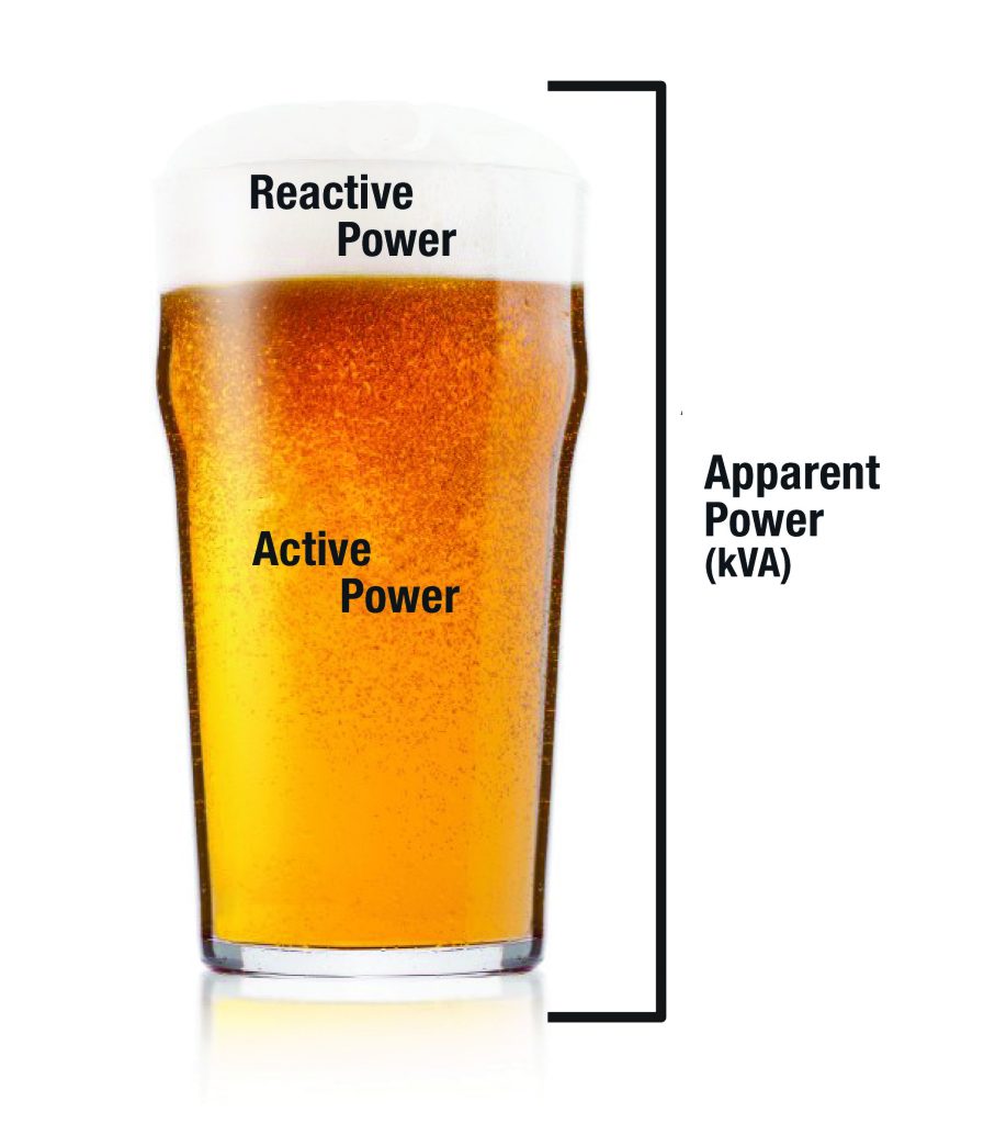
Speaking less technically, this scenario can be made easier to understand by likening it to a typical glass of beer. If you order a glass of draught beer, the whole glass you pay for is equivalent to the apparent power. But take a closer look – that beer has got a frothy head on it! The beer is the part you really want, and that’s equivalent to the active power, while the head, which makes no contribution to your refreshment, is equivalent to reactive power. A glass full of beer, with no head, would represent a power factor of 1 with no reactive power at all. In reality, that’s usually impossible to achieve and a power factor of 0.95 (corresponding to less than 5% froth) or better is usually considered acceptable.
So far, so good, but if electrical equipment inherently consumes active power, what can be done about it? Fortunately, it is possible to correct for power factor by adding a power factor correction (PFC) system. This usually takes the form of capacitors connected at the main distribution panel, or sometimes at other locations.
Many sites will already have some form of power factor correction (PFC) but as mentioned earlier, it is always a install and forget solution. If more equipment is installed on a site, or the type of equipment used on the site is significantly changed, the PFC system may no longer be adequate. Also, capacitors used for PFC can degrade over time and would eventually need to be replaced.
In fact, it is not uncommon for industrial installations to be operating with high levels of reactive power giving power factors of between 0.7 and 0.8. This is unnecessary and costly since measuring power factor is not at all difficult. It can be readily measured using portable test instruments, or alternatively, can be permanently monitored in real-time with constantly displayed values, along with a multitude of other useful parameters including voltage, current and energy consumption.
While specification of a PFC system to reduce reactive power requires knowledge of several factors including the voltage level and typical usage of the reactive loads on-site, the usage profile across the site, and the power quality required by the on-site loads, all of these are easily measured and/or calculated. And a properly designed PFC system will be a fraction of the cost of the savings it delivers.